How to Troubleshoot Vehicle Communication Problems?

Time:2026-09-09 Author:Sophia
0%

Modern vehicles depend on communication networks to coordinate the engine, transmission, brakes, airbag system, and body controls. When one module stops responding, the symptoms can seem unrelated. A warning light may appear beside a dead window, rough shifting, or a no-start condition.

Learning how to troubleshoot vehicle communication problems begins with careful observation. Record every warning message, recent repair, battery replacement, and intermittent symptom. A professional technician usually checks battery voltage, grounds, fuses, and connector condition before blaming a control module. A weak battery can create several misleading fault codes.

A quality scan tool can reveal missing modules, network codes, and communication history. However, the first code displayed is not always the root cause. Inspect wiring near the battery, engine, door hinges, and underbody areas. Look for corrosion, crushed insulation, loose pins, or moisture inside connectors. Use manufacturer service information and wiring diagrams when testing CAN or other vehicle networks. Do not replace expensive modules based on one unverified code.

Practical diagnosis requires patience.

Some faults disappear during testing. That makes them difficult.

Technicians should confirm power, ground, resistance, and network signals with suitable equipment. A multimeter helps, while an oscilloscope may expose distorted communication patterns. Diagnostic steps can vary by vehicle, network design, and software version. Even experienced professionals can misread an intermittent fault, so documenting each test matters. This guide explains reliable methods, common mistakes, and sensible decision points. It also recognizes an uncomfortable truth: communication failures are not always neatly predictable.
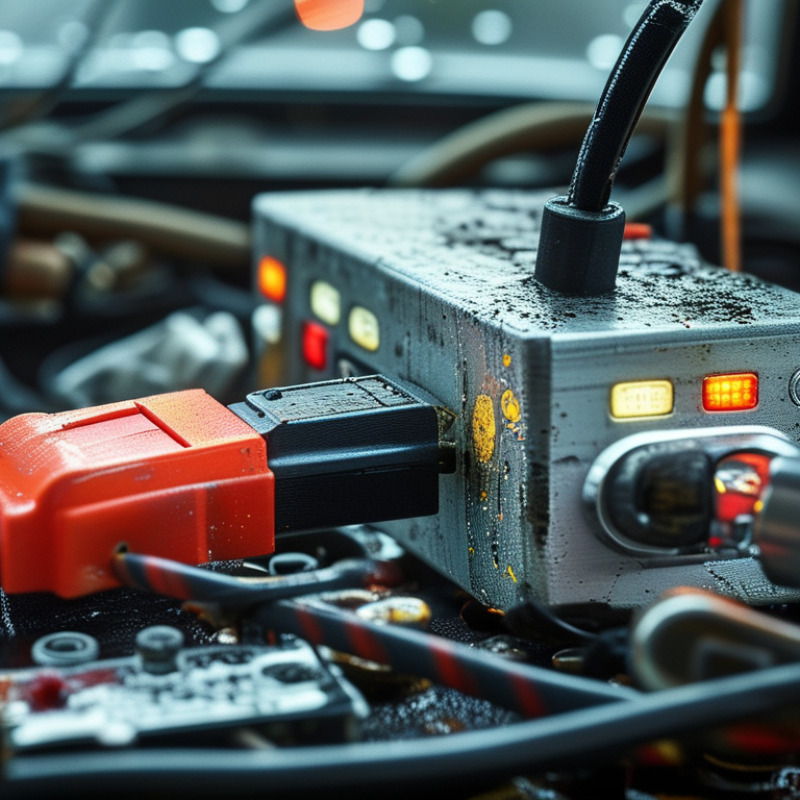
How to Troubleshoot Vehicle Communication Problems?

Identify Common Symptoms of Vehicle Communication Failures

Vehicle communication failures often appear as scattered, confusing symptoms. Warning lights may switch on without a clear mechanical cause. A scan tool might lose connection or show incomplete module data. Some dashboard displays can freeze, reset, or remain blank. Intermittent starting problems may also point to disrupted communication.

Watch for several systems failing together. Power windows, climate controls, lighting, or safety features may respond slowly or stop working. A vehicle may enter a reduced-function mode because one control unit is not sharing valid information.

Communication faults can come from weak battery voltage, damaged wiring, loose connectors, moisture, or incorrect repairs. In real workshop checks, technicians should record when the fault appears. Heat, vibration, and engine movement often reveal patterns that a stationary inspection misses. I have found that guessing from one warning light alone is unreliable.

Tips: Check battery voltage first. Inspect connectors for bent pins, corrosion, or moisture. Look for stretched wiring near moving components. Scan for related fault codes, not just one code. Compare symptoms before replacing any module. A forgotten ground connection can imitate a major network failure. Document every test, even the result that seems unimportant. Use accurate service information and suitable test equipment, then verify the repair with a second scan and a road test.

Check Power, Ground, Fuses, and Network Wiring

How to Troubleshoot Vehicle Communication Problems?

When a vehicle loses communication, check power and ground before blaming the network. A scan tool may show several missing modules, but one weak supply can create that pattern. Measure battery voltage with the ignition off, then test voltage at the affected module. A loaded test is more useful than a visual inspection. I have found clean-looking connectors with serious voltage loss under load.

Inspect the related fuses carefully. Do not rely only on sight; measure voltage on both fuse test points with the circuit active. A fuse can be intact while its socket has poor contact. Check the module ground with a voltage-drop test during operation. Keep the test leads secure. Loose probes can create misleading results. That mistake is easy to make.

After power and ground pass inspection, examine the network wiring. Look for crushed sections, stretched wires, moisture, loose terminals, or repairs with weak crimps. Twisted network wires should remain evenly paired near connectors. With power removed, resistance across the network may help identify missing termination, but compare the reading with the vehicle’s wiring information. Do not guess from one measurement. I once treated an unusual reading as a wiring fault, then found a connector was not fully seated. Network faults often need repeated checks, careful notes, and patience.

How to Troubleshoot Vehicle Communication Problems

This nominal high-speed CAN waveform shows recessive bus levels near 2.5 V on both lines and dominant signaling near 3.5 V on CAN-H and 1.5 V on CAN-L. Before diagnosing network faults, verify a resting battery voltage of approximately 12.4–12.7 V, a loaded ground voltage drop below 0.1 V, power on both sides of each fuse, and secure CAN-H/CAN-L wiring and termination.

Scan Control Modules for Diagnostic Communication Codes

Vehicle communication problems often begin with a simple mistake: scanning only the engine control module. A complete scan should include every accessible control module. Look for diagnostic communication codes, often identified as network or U-codes. These codes can reveal lost messages, interrupted power, or unstable data lines.

I begin with a health check of the vehicle battery and charging voltage. Low voltage can create several false communication faults. Then I connect a professional scan tool and record all codes before clearing anything. The scan report, module status, and freeze-frame details provide useful evidence. A code is a clue, not proof.

I inspect connectors, grounds, fuses, and visible wiring near the affected modules. Moisture around a connector can cause intermittent faults. A loose ground may produce confusing symptoms. I have sometimes trusted the first code too quickly, and that can waste valuable time. Network faults may appear in several modules, so their timing matters. Check whether the codes return after a controlled ignition cycle. Do not replace a module until power, ground, wiring, and communication signals are tested. It is a slower method. It is usually more reliable. Record each test and its result, because careful documentation can expose patterns that memory misses.

Test CAN Bus Signals and Network Resistance

How to Troubleshoot Vehicle Communication Problems?

CAN bus faults often appear as missing data, unstable readings, or several warning lamps. Begin with the vehicle switched off and the battery isolated according to service procedures. Measure resistance between CAN-H and CAN-L at the diagnostic connector. A healthy high-speed network usually reads about 60 ohms, because two 120-ohm terminators work in parallel. ISO 11898-2 defines these physical-layer principles. A 120-ohm reading may indicate one missing terminator. An open circuit suggests wiring damage or a disconnected module.

Use an oscilloscope when resistance appears normal but communication still fails. Check both wires against ground, then inspect the differential waveform. Dominant bits commonly show CAN-H near 3.5 volts and CAN-L near 1.5 volts. The exact voltage depends on the transceiver and network load. Look for sharp edges, excessive ringing, flat lines, or unequal amplitudes. A professional vehicle diagnostics survey published by the Automotive Aftermarket Industry Association has repeatedly identified electrical and communication faults as major causes of repeat repair visits. That finding matters. A perfect resistance result does not prove a healthy network.

Tips: Record resistance before reconnecting power. Back-probe carefully, without spreading terminals. Compare waveforms during ignition-on and active communication. Check grounds under load, not only at rest. I have seen technicians replace modules too early. That habit deserves review. Wiring, termination, and grounding should be tested first. Save screenshots with time, connector location, and measured values. Insufficient notes can make a correct diagnosis difficult to repeat.

Repair Faults and Verify Stable Vehicle Communication

Vehicle communication faults rarely disappear after clearing codes. A warning may point to a weak power supply, damaged wiring, poor grounding, or a congested data line. I begin with the vehicle battery, ignition voltage, and ground points. Then I inspect connectors for moisture, bent terminals, and loose locks. Small details matter. A clean visual check often prevents unnecessary module replacement.

Using a suitable scan tool, I record all fault codes before making repairs. Network-related codes should be compared with the vehicle’s wiring diagram and communication layout. I measure resistance only when the circuit is powered down and the procedure allows it. Unexpected readings can reveal an open circuit or an unwanted short. After repairing a terminal or wire, I secure the harness away from heat and sharp edges. I once trusted a code too quickly; the real cause was a damaged ground strap. That mistake changed my process.

Stable communication requires more than one successful scan. I clear the faults, cycle the ignition, and check every related control unit again. A road test should include vibration, temperature changes, and normal electrical loads. Watch for delayed messages, warning lights, or functions that stop briefly. If the fault returns, I compare live data with the original records instead of guessing. The result should remain consistent after repeated starts. Some intermittent faults need time. That is frustrating, but rushing can hide the repair’s weakness.

FAQS

: What should be checked before blaming the vehicle network?

: Check battery voltage, module power, grounds, and related fuses. A weak supply can make several modules appear offline. Do not trust appearances alone.

Why is a loaded power test useful?

A loaded test reveals voltage loss during actual operation. A clean connector may still fail under load. That detail is easy to miss.

How should related fuses be inspected?

Measure voltage at both fuse test points with the circuit active. An intact fuse can still have poor socket contact. Visual inspection is not enough.

How can a module ground be tested?

Perform a voltage-drop test while the module operates. Keep the test leads secure. Loose probes create false readings.

What wiring problems can interrupt communication?

Inspect for crushed wires, stretched sections, moisture, loose terminals, and weak repairs. Twisted network wires should stay evenly paired near connectors. Small damage matters.

Can network resistance testing confirm a wiring fault?

Resistance testing may reveal missing termination with power removed. Compare the reading with the vehicle’s wiring information. One unusual measurement proves little.

Which modules should be scanned for communication codes?

Scan every accessible control module, not only the engine module. Network or U-codes may indicate lost messages or unstable data lines. A code is only a clue.

When should a control module be replaced?

Test power, ground, fuses, wiring, and communication signals first. Record all codes before clearing them. I have trusted the first code too quickly. That wasted time.

Conclusion

Learning how to troubleshoot vehicle communication problems begins with recognizing symptoms such as warning lights, intermittent module operation, failed scans, or devices that cannot exchange data. Start by checking the battery supply, grounds, fuses, connectors, and network wiring for looseness, corrosion, damage, or unexpected resistance. These basic inspections can reveal power or connection issues before more advanced testing is performed.

Next, use a suitable diagnostic scanner to check whether each control module responds and to identify communication-related fault codes. Test the network signals with appropriate measuring equipment, confirming that the CAN lines show stable activity and correct resistance when the system is powered down. After locating the cause, repair damaged wiring, terminals, power supplies, grounds, or network components as necessary. Clear the stored faults, rescan every relevant module, and perform a road test to verify that communication remains stable under normal operating conditions.

Sophia

Sophia

Sophia is a dedicated marketing professional with an exceptional depth of knowledge about her company's products and services. With a keen understanding of market trends and customer needs, she crafts insightful blog posts that not only inform but also engage readers, enriching the company’s online......