When a warning light appears, automotive diagnostic equipment helps turn a vague symptom into useful evidence. How does automotive diagnostic equipment work? A scan tool connects to a vehicle’s diagnostic port and communicates with its electronic control modules. These modules monitor information from sensors, such as engine temperature, oxygen levels, and wheel speed. The tool can retrieve fault codes, display live readings, and sometimes run system tests. A mechanic might watch engine data change on a screen while the vehicle idles, then compare those readings with the manufacturer’s specifications.
A code is a clue, not a verdict. It identifies a detected problem or unusual reading, but it may not reveal the failed part by itself. A loose connector, damaged wire, or faulty sensor can sometimes produce similar symptoms. Skilled technicians combine scan-tool results with inspection, service information, and targeted tests before recommending repairs. That distinction matters. Diagnostic equipment also varies: a basic reader may show engine codes, while advanced equipment can access more vehicle systems and perform additional functions. Results depend on the vehicle, the tool, and the technician’s interpretation. Even accurate equipment has limits. It cannot hear every rattle, see every leak, or replace careful reasoning. Understanding how these tools collect and present evidence helps drivers follow the diagnostic process and ask clearer questions about the next repair.
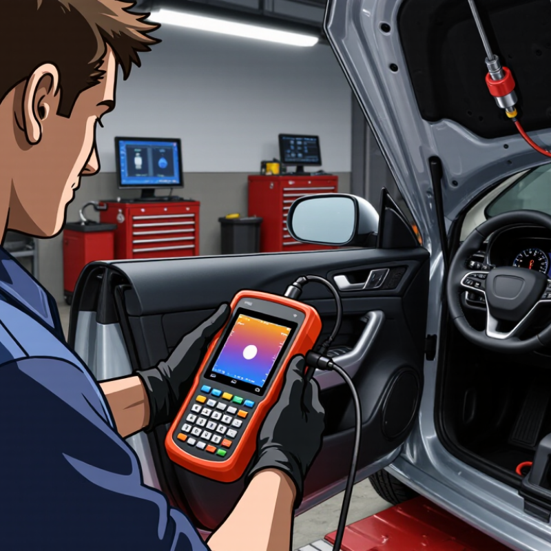
Automotive diagnostic equipment is designed to collect and organize information from a vehicle’s electronic systems. A scan tool connects through the diagnostic port, often beneath the dashboard, and retrieves fault codes and live data. These readings can include engine temperature, oxygen sensor activity, and battery voltage. When a warning light appears, the stored code helps narrow the search. It does not identify every failed part.
Some equipment can display freeze-frame data, showing conditions recorded when a fault occurred. More advanced tools may run system tests or command certain components, such as a cooling fan, to operate. This helps a technician compare expected behavior with what the vehicle actually does. The tool is only one part of the process. A loose connector, damaged wire, or intermittent fault may need hands-on inspection.
Good diagnostic work combines equipment readings with service information and practical checks. A code can point toward a circuit, not necessarily a faulty sensor. That distinction matters. Even experienced technicians can follow a misleading clue, especially when a problem comes and goes. Equipment makes evidence easier to access, but careful interpretation still takes time.
Automotive diagnostic equipment connects through a vehicle’s diagnostic port, often located beneath the dashboard near the steering column. The tool’s cable or wireless adapter links to this port and receives power or data, depending on its design. The connector should sit firmly, without force. A loose fit can interrupt communication.
After connection, the tool communicates with the vehicle’s electronic control modules using supported protocols. It may request stored fault codes, sensor readings, or system status. The vehicle then sends available data to the tool for display. Some tools show live information, such as engine speed or coolant temperature, while a technician observes changes. The process is not always seamless: a weak vehicle battery, an incompatible tool, or a damaged port may prevent a reliable connection. A code is a clue, not a confirmed diagnosis.
Tips: Turn the ignition to the position specified by the tool’s instructions. Keep the connector steady. If communication fails, check the port and vehicle battery before repeating the scan. Note any warning lights and conditions, such as a cold start; small details can help interpret results.
When a scan tool communicates over a vehicle’s CAN bus, it reads voltage changes on the CAN High and CAN Low lines. The chart shows typical nominal signal levels: both lines sit near 2.5 V when recessive; during a dominant signal, CAN High rises and CAN Low falls.
Typical values are approximate; actual readings can vary by vehicle, network design, and measurement conditions.
Automotive diagnostic equipment retrieves data by requesting it from a vehicle’s electronic control units. A technician connects a scan tool to the diagnostic socket, usually beneath the dashboard. The tool communicates using the vehicle’s supported protocol; many newer vehicles use Controller Area Network communication. SAE J1979 describes standardized diagnostic services, while ISO 15765-4 specifies emissions-related communication over CAN. The tool can request live values, such as engine speed or coolant temperature, and stored diagnostic trouble codes. A code usually identifies a monitored system and fault condition, not the failed part itself.
A code is a clue, not a verdict.
Fault codes follow formats defined in standards such as SAE J2012 and ISO 15031-6. The first character indicates a broad system category, while later characters narrow the reported condition. Some codes are standardized; others are specific to a vehicle’s manufacturer. S&P Global Mobility reported that the average age of U.S. light vehicles reached 12.6 years in 2024, so tools may encounter varied generations and communication requirements. J.D. Power’s 2024 U.S. Vehicle Dependability Study recorded 190 problems per 100 vehicles, based on owner-reported issues in three-year-old vehicles. These figures describe the service context, not scanner accuracy. It is easy to overtrust a code. Checking freeze-frame data, wiring, and sensor readings can reveal whether the code reflects a failed component or a symptom.
Diagnostic results are clues, not verdicts.
A scan tool retrieves fault codes and operating data from a vehicle’s control modules. Each code points to a detected condition, such as an airflow reading outside its expected range. It does not automatically identify a failed part. A code is a clue. For example, an emissions-related code may come from a loose connection, damaged wiring, or a sensor problem. The technician checks the code description, vehicle symptoms, and service information together. Freeze-frame data can show engine speed, temperature, and load when the fault appeared. That snapshot adds useful context.
Live data helps reveal what is happening now. A technician may watch sensor readings while the engine idles, then compare them during acceleration. Values should be checked against specifications for that vehicle and test conditions. One unusual reading may be caused by another problem upstream. So technicians often test circuits, inspect connectors, and confirm power or ground before replacing parts. This step can feel less certain than reading a code. It should. Diagnostic tools report patterns, and people must verify what those patterns mean. After a repair, the system is checked again to see whether the fault returns and whether related readings behave normally.
A repair is not verified when the warning light simply disappears. The technician should clear the stored fault, then repeat the conditions that triggered it. That may mean a cold start, a short road drive, or switching on the air conditioning while watching live sensor readings. The scan tool can show whether the fault returns and whether required onboard monitors have completed their checks. A smooth dashboard is not enough.
The 2024 U.S. Vehicle Dependability Study recorded 190 owner-reported problems per 100 vehicles after three years of ownership, four more than the prior year. This measures reported vehicle problems, not repair failures, so it cannot predict whether a specific fix will hold. Still, it shows why checking only once can be a weak habit. On a real repair, I would compare before-and-after codes, confirm stable readings, and test the affected feature under safe, repeatable conditions. Sometimes the fault stays away only because the original conditions were not recreated. That deserves a second look. A clean scan is useful evidence, not proof by itself.
| Diagnostic step | Equipment and data | Example finding before repair | Follow-up test | What indicates a successful repair |
|---|---|---|---|---|
| Read fault codes | A scan tool retrieves diagnostic trouble codes (DTCs), status, and available freeze-frame data from vehicle control modules. | A stored or pending misfire code identifies a cylinder and helps show when the fault occurred. | After the repair, rescan for current and pending codes. If required, complete the manufacturer-specified drive cycle and scan again. | The original fault does not return under the test conditions, and no related current or pending code appears. Some readiness monitors need driving time to complete. |
| Compare live sensor data | A scan tool displays values such as engine speed, coolant temperature, fuel trims, and misfire counters. | A misfire counter may increase for one cylinder when the engine is tested at the conditions associated with the complaint. | Repeat the same operating conditions while watching the relevant live data and counters. | The symptom is absent and the affected counter does not continue to rise. Values should be assessed against vehicle-specific service information. |
| Check electrical circuits | A digital multimeter measures voltage, resistance, and voltage drop; an oscilloscope can show changing electrical signals. | A voltage-drop test may reveal excessive loss across a connection while a circuit is operating. | Repeat the measurement under the same electrical load after repairing the connection or circuit. | Voltage drop and signal behavior meet the applicable circuit specifications, and the component operates consistently. |
| Verify fuel-control behavior | Scan-tool live data shows short-term and long-term fuel trims, which indicate how the control system is adjusting fuel delivery. | Persistently high positive fuel trims can be a clue to an overly lean condition, such as an air leak, but are not proof of a single cause. | Repeat readings at comparable idle and engine-load conditions after the suspected cause is repaired. | Fuel-trim values move toward the vehicle’s expected range and the original drivability symptom is no longer present. |
| Test for fluid or pressure leaks | A cooling-system pressure tester checks whether the system holds pressure; a mechanical gauge may be used for other specified pressure tests. | A pressure reading falls during the test, suggesting a leak that needs to be located and confirmed. | Pressurize the system to the service-manual test value and repeat the inspection for the specified duration. | Pressure remains within the permitted limit and no leak is found. Test pressure and duration depend on the vehicle and system. |
| Check wheel-speed signals | A scan tool or oscilloscope monitors individual wheel-speed sensor data during a controlled test. | One wheel may report an implausible reading or drop out compared with the other wheels while moving. | Repeat a safe, controlled road test and compare all wheel-speed readings through the same driving conditions. | Signals are plausible and consistent with vehicle movement, with no repeat fault code or ABS warning indicator. |
| Confirm emissions-system readiness | A scan tool checks the malfunction indicator lamp status, DTCs, and emissions-monitor readiness. | A fault may have set a code or prevented one or more monitors from completing. | Follow the prescribed drive cycle, then check codes, warning-lamp status, and monitor results again. | No related fault returns and the required monitors show complete. Monitor completion can require specific driving conditions. |
| Important: The examples describe common diagnostic methods, not universal pass/fail limits. Test conditions, specifications, and drive cycles vary by vehicle; use the applicable service information and observe safety procedures. | ||||
It is often beneath the dashboard, near the steering column. Check the vehicle’s layout before reaching for it.
Its cable or wireless adapter links to the port. The connector should fit firmly, not be forced.
It can request stored fault codes, system status, and live readings. Examples include engine speed and coolant temperature.
Not usually. It points to a monitored system or condition, so wiring and sensor readings still need checking.
Check the connector, diagnostic port, and vehicle battery. A weak battery or damaged port can interrupt communication.
A cold start or warning light can help explain the results. Small details matter more than they seem.
Clear the stored code, then repeat the conditions that triggered it. Watch readings during a safe, short drive.
No. Confirm stable readings and completed system checks. I would still question a fix if the original fault conditions were never repeated.
How does automotive diagnostic equipment work? It helps technicians identify problems by communicating with a vehicle’s onboard systems. A diagnostic tool connects through the vehicle’s designated diagnostic port, allowing it to request information from electronic control units that monitor components such as the engine, transmission, and emissions systems.
The equipment retrieves stored fault codes and live data, including sensor readings and operating conditions. Technicians interpret these results alongside the vehicle’s symptoms and relevant system information, since a code points to an area for investigation rather than always identifying a failed part. After completing a repair, they can clear applicable codes, run the vehicle or specific systems again, and review fresh data. These follow-up tests help confirm that the original issue has been addressed and that no related faults remain.

Manata Scanner